Back to Contents
Back to Railways Page
Link to Sitemap
Back to the second page, erm previous page. Well you know what I mean.
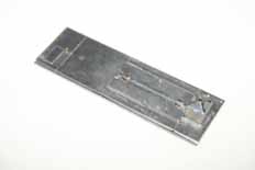
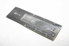
I decided that with the cab assembled now might be a good time to get the bonnet a bit further through it's construction. The top needed a few bits and pieces fitted. Principal amongst these was the silencer box. This is cast in whitemetal with a shallow hole in its top for the exhaust port. In the process of opening this out further I managed to drill the short 'chimney' off the top of the box. After I'd finished my exercise for the day (Oh b***** and b****!) I realised it was an opportunity in disguise. A rumage through my boxes turned up a length of 1.5mm o/d brass tube which would be just the job. So the hole in the top of the silencer was drilled 1.5mm dia. and a slightly larger hole was drilled between the two mounting holes on the bonnet. The silencer can then be fitted and the length of tube pushed in and soldered from underneath. The excess tube length was then removed with a piercing saw (0000 blade). I ran a tapered dental burr down the top of the tube (by hand; a minidrill would be too agressive at this stage) to thin the wall of the tube until I was happy with it. So the result was a much stronger and finer exhaust pipe than that supplied. A recommended improvement. Mind you - this form of silencer only applies if you're modelling either DR or CSD...
Of the other details the most obvious absentee is the bell. I've only found one pic of a DR V36 with a bell and it wasn't '022. The unused fixing holes were filled with solder and the required holes for the other parts were drilled. I was intending to fit the lift rings at this stage, but after seeing where the drilled holes came out I decided to leave them until later. The grab handles on the engine access panel were fitted at this stage however; so too was the small lug that goes towards the cab end. The lamp will be left until the bonnet top is safely installed on the sides and front, that way it remains safe from handling damage should any filler or filing be needed.
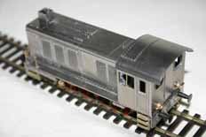
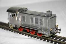
Now that's a surprise isn't it? The cab, bonnet etc. were balanced on the chassis/footplate assembly to check for fit and weight. The front and rear fixing screws were tried and it was no surprise to find that the holes in the running plate needed 'stretching' slightly in order for them to fit. We're nearly there now, but there are a few things left in the packets and a couple of small details require fiddling onto the front and sides of the bonnet. I weighed the loco at this point. It was almost bang on the 300g weight I'd be looking for an 0-6-0 loco to have. Good news indeed.
And at least it's starting to look like a railway engine now...
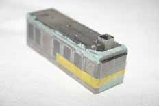
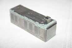
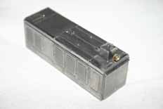
I decided to assemble the bonnet top to the sides and front at this point - it helps keep the assembly strong for the final detailing. It was then the time to apply some strategically positioned filler. I used Loctite Auto 'Professional Body Filler' (Plastic Padding) as it's fast and also dries slightly flexible, so any movement of the body won't crack out the filler. It also doesn't shrink in normal use and even seems reasonably stable at soldering temperatures. The only potential problem is that it has a slightly soft texture and fine grain which means it clogs files. So I keep a steel bristle brush handy to clean the files and always follow up on the model with wet and dry paper (used wet) to finish the surface.
The masking tape used to prevent blocking the front radiator grille with filler is an old trick picked up from my aircraft modelling days. Tamiya masking tape is absolutely the best stuff. Period. Most of the filler applied to the long side/top seam wasn't needed; but I found that it was well worth applying it around the front/top of the bonnet. The tape is pulled off just as the filler starts to go off. It's then left to cure hard for an hour or two before the filler in the front grille is carefully scraped smooth with a fresh curved scalpel blade. Don't try and cut the filler out; use the side of the blade gently as a scraper. The rest of the filler was dressed down normally with files and wet and dry paper.
At this stage I was intending to fit the rest of the details in place with solder. However, I tried that with the lift rings and managed to leave a soldering-iron shaped dent in the top of the bonnet (more exercise!); so I decided to put all the rest of the bits on with superglue. The front lamp is going to be pretty vulnerable though; so this has been soldered. The damage was hastily filled with 70° solder and filed smooth, the shiny patch on the top of the bonnet to the side of the silencer is all that remains of the damage in the third picture. Thankfully...
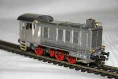
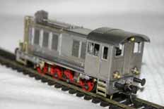
Ready for the paint shop - the bonnet and cab are now soldered together. The lift rings and handrails have been fitted with superglue. The loco I'm modelling is in a very plain livery, green above the running plate, red below; so the supplied blackened cab handrails were dispensed with in favour of some new ones made from the brass wire provided. At this stage I also worked out and trial fitted the Kadee couplers too.
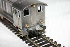
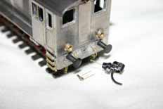
A bit more detail on the fitting of the Kadee couplers. I decided to use a variation of the method used on my BR50. So I used an Alan Gibson coupling hook with a loop of wire through it to support the front of the coupler, the back is supported on a pin that goes through the bufferbeam. Some slightly tricky drilling is required on the Kadee #18 coupler head
itself...
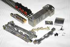
The parts disassembled for painting. The full set of brakegear is still not fitted - the insulated side will go on after painting. I joined together the two sprues with brakeshoes on them to make it easier to clean, hold and paint. The castings have been tidied with a file and then burnished; just like all the others so far used. You can also (just) make out the notch filed out of the keeper plate that's required to clear one of the fixing screws - you may remember me referring to it earlier. Noticable by it's absence are the brake pull rod parts. These will be made up as the rest of the chassis goes together and then painted in situ.
I'm sure it won't be much of a surprise that the next page covers the painting of the model...


