Back to Contents
Back to Tips and Tricks
Link to Sitemap
Preparing Slater's 0-gauge wheels for split-axle pick-up - Page 3 of 3
A radical solution (Type 3)
Well, you now join us having completed extensive 'proof of concept trials' with split axles!
Using Type 1 and Type 2 split axles we've now managed to build locos with this style of pick up on all axles. We've even managed to get other people using them reliably and a friend considers them easier and more reliable than any other means of pickup.
I don't think he's wrong, either. A little extra effort during the build means that you may be in the fortunate position of never having to do any maintenance on your locos for their entire lives. Or yours; whichever comes sooner...
The type of axle being assembled here is a little more complicated than either of the other two we've produced so far. It requires a bit more care and the purchase of some specific materials and tools which you may not have to hand in your toolbox. On the plus-side, it's still self-jigging, so you won't be needing a lathe or any clever special-to-type tooling. It's also a very good way of putting double insulated breaks either side of a gearbox; so you probably won't need to make many of them; the other types are probably better for plain axles anyway.
The Tools and Materials
For this variant of split axle you will need the following materials, consumables and tools:
- An axle (assumed to be Slater's).
- 2mm diameter pultruded GRP rod.
- DevCon '2-ton' adhesive.
- Piercing saw frame and No.0 blade.
- Used fine wet-and-dry paper.
- An old needle file.
- 2mm HSS drill.
- 1mm HSS drill.
- 0.5mm or 0.7mm HSS drill.
- Miniature diamond slitting disc and mandrel (optional).
- Masking tape.
- A miniscule quantity of fine oil (Seuthe, Hobbylube, clock oil or sewing-machine oil would all be fine).
- A scriber and/or pair of dividers
- Toolmaker's clamp (recommended, but perhaps not essential)
- Centre punch.
- Hammer.
- Small power drill (i.e. Dremel, or equivalent), ideally with collets, but a normal chuck should be fine.
- Cocktail stick (or toothpick, if you prefer!)
- Multimeter or simple circuit tester.
- Magnifying glass (optional)
- Bright light or torch (optional)
- 6BA plug (3rd) tap (optional)
At this point you're probably wondering about the '2mm diameter pultruded GRP rod' aren't you? Well, don't panic; it's cheap and fairly readily available. At the time of writing I was able to buy a lifetime's supply of 2.5m (yes, 2.5m!) for £2 (yes, £2!) from my local kite shop, Bristol Kitestore (external link opens in new window). Most of these places will do mail order (the stuff is remarkably resilient and survives being coiled and posted), or you can take a stroll to your nearest vendor. Just a quick word of warning; some shops might try to sell you a carbon-fibre equivalent on the basis of greater strength and resilience. It's useless for our purposes though as most carbon-fibre composites are conductive...
If you really get into split axles then you might want to invest in the diamond slitting discs. Mine cost around £5 for five with a mandrel from a local tool stockist. The main reason for having them is that they reduce the chance of the GRP rod fraying when cut and allow the rod to be quickly and cleanly cut to length. An alternative is to tightly wrap masking tape around where you want to make the cut. A fine-toothed saw can then do 'the business' - a piercing saw is ideal, although it's likely to get blunt pretty quickly.
The Technique
I was told about this approach to making split axles by a friend of mine, Ed Whailey. He uses a lathe to do most of the drilling and cutting but it is entirely safe and sensible to do it at the bench; it may even be less stressfull to the axle. Those of you who have lathes will, I'm sure, be able to work out how Ed does it as you read this description:
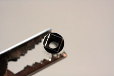
The first thing to do is to drill the whole way through the length of the axle 2mm diameter. This isn't as onerous as it sounds. I hold the axle in the chuck of my hand drill, with the 2mm drill in the Dremel and then carefully drill in each end of the axle until the hole is complete. The slightly arty picture above shows the situation afterwards, incidentally I think it's the only time I've ever found a use for a 'helping hands' tool!
With the hole made it's then time to work out how long a piece of GRP rod you need to go down the centre of the axle, leaving enough at each end to be able to tighten the screws fully 'home'. There is some maths to do if you want to be precise, or you can copy the 24mm length I have used. After cutting off the length it's worth quickly dropping it down the hole in the axle and making sure you can do the screws up fully. If you can't then the rod needs to be reduced in length. After doing this quick check, undo the screws and poke out the GRP rod section - that's what the cocktail stick is for!.
You now need to mark the axle where you want the insulation breaks to be. In the example shown here the position of the breaks are chosen purely to demonstrate the principle, they're about as far apart as I'd be prepared to make them at 20mm. That leaves only a couple of mm of GRP rod in each stub end, although it will be keyed into the screw thread with adhesive. In many cases I'd want the insulation breaks to be closer together; pretty close to the width across the gearbox bearings, plus a smidge to make sure the insulation isn't bridged by slack in a bearing. Marking these lines in with a pair of dividers will help make sure the gearbox is mounted centrally on the axle. of course, if your gearbox is asymmetric in layout or needs deliberate mounting off-centre than you may have to think of another way to mark the position of the break(s)!
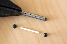
This next step is an enhancement over the basic principle. This helps 'lock' the parts of the axle together with adhesive. An alternative might be to continue the 6BA screw thread the whole way through the axle: your choice. The technique detailed here works by putting a set of burrs on the inside of the axle tube and providing an epoxy 'key' to the joins. This is done using the 1mm drill to go through the axle at the point of the lines you've just marked, holding the axle end in a toolmaker's clamp and drilling vertically on a well-supported flat surface is a good idea. The smaller drill can then be used to drill a few slightly more random holes into the axle; three on the middle section and one or two in each stub will be enough. I'd normally distribute them around the axle, but in this photo they're in a line, so you can see them all in one image. Once you reach this stage it's worth having a quick poke down the length of the axle to clear any swarf out. Another use of the cocktail stick, perhaps?
A similar job of keying the GRP rod can be done now by marking the axle with an old needlefile. It's worth making sure that the key marks are distributed over the surface of the rod and within reason it's a case of 'the more the merrier'.
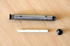
The photo above shows the parts ready for assembly, which can begin now. The first job is to lightly oil one of the axle-end screws and fit it to the axle. Now you can mix up a quantity of DevCon 2-ton and a good dollop can be fed into the open end of the axle. I then carefully blew down the axle so the adhesive is in place. The GRP rod is then covered with a dollop of adhesive and pushed into the axle. This action will force adhesive through the holes in the axle and hold the whole lot together. A further dollop of adhesive can be put into the end of the axle behind the GRP rod. The second axle end screw is then oiled and screwed into the open end of the axle, which will push out more adhesive through the holes.
At this stage removing most of the adhesive from the surface of the axle is a good idea, it can then be wrapped in masking tape to retain the adhesive as it cures. Once the initial cure is complete it's probably worth unpeeling any excess adhesive from around the axle ends, screws, etc. The axle can then be left to harden off completely.
The oil on the screws will make it possible to remove them after the adhesive has cured, although it may still be tricky! At this stage I want the screws out (if they don't come out you're back to square one with a new axle). If you're really fastidious (and have a 6BA plug tap handy) you can quickly run that down each end of the axle to remove any adhesive that may have found its way into the threads. I don't clean off the excess adhesive just yet, there's a couple more lots of glueing to do and I find it easiest to clean it all off in one go at the end.
The next job is to cut the first insulation gap through the steel axle where we marked and drilled it earlier. This is a job for a piercing saw and requires some care: you don't want to cut into the GRP at all if possible, although light marks won't cause any significant problems. You may need to use a bright light and a magnifying glass to see down the cut as you make it. The multimeter can then be used to make sure that the insulation gap has been created as intended.
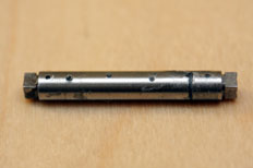
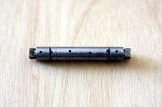
Once you're comfortable with the insulation gap it can be packed with DevCon, wrapped with tape and left to cure. Once fully cured the other insulation gap can go in, as described in the previous paragraph, and then it too can be filled with adhesive, taped and left to cure.
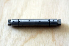
Now is the point at which you can remove any tape and use your old wet and dry paper to polish off the excess adhesive and put a nice shine on the axle. It's worth doing a full check with the multimeter, just in case a piece of swarf or similar has bridged an insulation cut. If that has happened, don't panic; re-cut and re-fill the slot.
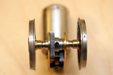
It's now ready for use with a set of suitably modified wheels (the modification to the wheels is covered on the first page on split axles) and when used with suitable bearings and something like the ABC gearbox shown here might look something like the photo above...


