There are two main issues to building electrically gapped gearboxes:
- Electrically (but not mechanically!) separating the gearbox into two or three parts.
- Electrically (and never mechanically) separating the axle into two or three parts.
Secondary to those issues is the selection of appropriate materials to allow for the insulation breaks. This is without adversely affecting the mechanical properties, including long-term strength and stability of the components being modified.
There is another issue, regarded by some as a subtlety – we don’t want to pass current through the gears as this would lead to electro-erosion. This would affect the surfaces and wear of the gear teeth in the longer term. Depending upon how the insulation is set up it might also lead to a direct short-circuit of your chassis!
This latter problem might be expressed more simply as ‘keeping all gears on the same side of the insulation break(s)’.
Potential insulation schemas
After spending a short while scribbling things in my log book, I came up with a number of ideas as to how gearboxes and axles could be split depending upon the width of the drive gear, gearbox, frames and how they’re installed. In order to keep this page as ‘authentic’ to my thought processes as possible (!!!) the illustrations below represent a set of ‘tidied’ diagrams from my log book and remain hand-drawn.
I hope they’re useful and will explain them as we go, before describing in more detail the solution arrived at for Ironside, and how it’s actually made. In general the approach has been ‘one break good, two breaks better’. While this certainly holds true electrically, for mechanical strength and accuracy it pays to keep the number of insulation breaks down. In practise I settled on only a single insulation break for Ironside’s gearbox, which I hope will become clear.
Wide gearbox (also good for fixed driven axles)
Narrow gearbox
Medium gearbox
Offset (asymmetric) gearbox
Assembling the axle
This type of split axle uses exactly the same techniques as the Type 1, but results in a more compact joint and was my first attempt at developing a split axle that could be used with a gearbox. It is slightly more complicated to make and perhaps not quite as strong as the first style; but is 'self locking' and 'self jigging', so once complete I doubt there is much in it.
There is another style of split axle, which we're referring to as a Type 3, which is a little more complicated, but allows the use of a wider variety of gearboxes without modification to the gearbox.
The Tools and Materials
To make this variant of split axle and the associated gearbox you will need the following materials, consumables and tools:
- An axle (assumed to be Slater's).
- An etched, fold-up gearbox kit.
- DevCon '2-ton' adhesive.
- Piercing saw frame and No.0 blade.
- Used fine wet-and-dry paper.
- 1mm HSS drill.
- Masking tape.
- A scriber and/or pair of dividers
- Toolmaker's clamp (recommended, but perhaps not essential)
- Centre punch.
- Hammer.
- Small power drill (i.e. Dremel, or equivalent), ideally with collets, but a normal chuck should be fine.
- Multimeter or simple circuit tester.
- Double-sided copper clad paxolin
- Drills and/or files
- A countersink drill bit
- A hand drill
- The motor that will be used with the gearbox
- A spare axle (optional)
- Soldering iron
- Solder
- Flux
- A length of brass wire (optional)
The Technique
Insulating a gearbox (medium width gearbox)

This gearbox uses an insulating washer made from paxolin to mount one of the bearings clear of the rest of the frame. So this first shot shows the components from the Agenoria 'Ironside' kit (gearbox frame, worm, gear and bearings) together with parts cut from scrap nickel-silver to strengthen the gearbox and a home-brewed double-sided copper-clad paxolin washer. It helps if the washer is made from reasonably thick material as you will see from the assembly method outlined below. The washer is carefully drilled and opened out to be a smooth fit on one of the bearings and is then cut out and shaped to a convenient outside diameter (in this case to match the gearbox frame) before being de-burred.
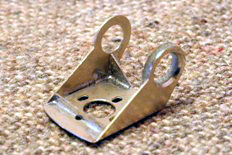

The next stage is quite tricky to show photographically, so in part we're back to sketches, I'm afraid. This will give you an accurately-positioned insulated bearing:
- First-off make sure of the fit of the washer on the bearing and ensure it's a nice smooth fit, ideally without any slop.
- The bearing can then be fitted (not soldered) to the washer.
- Open up the hole in the gearbox to take the bearing with the washer in place underneath the flange on the bearing.
- Solder tack the washer to the gearbox frame.
- Pop the bearing out of the washer/frame assembly. Use a soldering clip to hold the washer in place and then complete the solder bond to the frame.
- Wash and dry the assembly before using the countersink bit to open out the hole in the frame/washer from the frame side only. There are two views of the gearbox at this stage shown above.
- Pop the bearing back into the hole to ensure that there's a clear gap between the gearbox frame and bearing. If you're okay up to this stage the gearbox assembly can be completed.
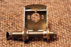
We're now back to conventional assembly techniques for the rest of the gearbox. The frame of the gearbox is formed and the folds reinforced with solder. The strengtheners are added to make sure the the frame is (and will remain) square and strong. The bearings are fitted now - the photo showing a spare axle in use to align them. The axle can then be removed and now is a good opportunity to do a quick continuity check to make sure our 'insulated' bearing is genuinely insulated.
After washing the flux off and drying the now-complete gearbox frame, the groove around the insulated bearing can then be filled with DevCon. And you're correct, I still haven't done it...
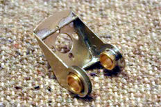
Once you reach this stage the gearbox should look something like this view - the strengthening components are optional, of course...
Making the 'Type 2' axle
With this axle type I will assume that you're using it for a specific purpose; the application here is to allow the mounting of gearboxes, but you might use two of this type of insulation break in one axle if you need to put a centre-beam style of compensation into your model. Your first challenge is therefore to work out where on the axle you want the break to be. The break can be made much more compact than the 'type 1' version, but I wouldn't aim for anything much less than about 2/3rds of the axle diameter (roughly 1/8").
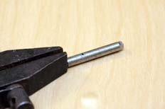
Having marked out the area of the joint on the axle I mount it up in a toolmaker's clamp and drill straight through the axle on one of the marks with the 1mm drill; this provides a starting hole for the next stage.
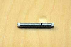
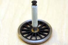
The second part of the job is to make a 'U'-shaped cut lengthways in the axle. If the top of the 'U' is tightened up then the part will remain locked together like a jigsaw-puzzle piece even when the second and third cuts are made later. The hole and 'U'-shaped slot can now be filled with DevCon, wrapped with masking tape and left to cure off overnight.
The second photo above shows the axle supported upright with an oiled screw in the visible end; this is because the Slater's axles are hollow over much of their length and I realised that the glue was weeping through into the screw hole in the end of the axle through one of the cuts I'd made. Supporting the axle upright with an oiled screw in the end will stop the threads getting blocked while allowing the adhesive to bond the axle: assuming the tape is wound pretty tight to hold the adhesive in place!
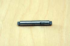
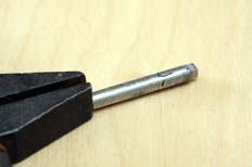
The next stage requires a little care, for although the 'U'-shaped cut is self-locking, it's going to become a little vulnerable once the next cuts are made, once the next lot of gluing has been done it'll be fine though. By the way, if you get a 'click' out of the axle, detect any movement in the join, drop it, launch it into a low sub-orbital flightpath or give it a nasty look during this stage then throw it away and start again...

The second set of cuts are made at an angle in towards the top of the 'U'-shape. Once both cuts have been made it's worth quickly checking the insulation with the multimeter. The two new slots can then be filled with DevCon, wrapped with tape and left to cure.
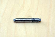
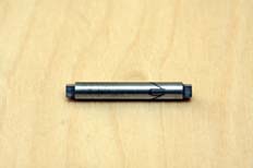
Once cured the tape can be removed and the old wet and dry paper used to polish off the excess adhesive and put a nice shine on the axle. And that's it. It's now ready for use with a set of suitably modified wheels.
Completion
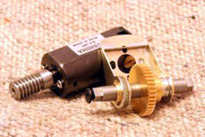

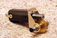
I tend to run-in gearboxes on the bench long before they come into contact with the rest of the model. In fact I also run-in the motor before it reaches the gearbox. My usual drill is to use a good quality analogue controller and run the motor for 15 minutes one way, 15 minutes rest, 15minutes in the other direction, 15 minutes rest and repeat...
You may also have picked up on one of my tricks for reducing noise in this type of gearbox - there's a washer between the bearing at the front of the motor and the worm. This stops slop in the motor shaft which can be a source of noise, but allows the shaft to turn easily.
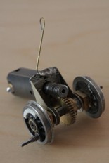
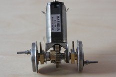
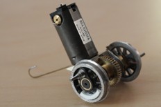
And here is the assembly complete for a quick check and test. The wheels have had their balance weights made and fitted, the crankpins are in place, the rims have had wires run down to the hubs, the split axle is installed in the gearbox with the hornblocks.
You'll also have noted the elegantly-shaped piece of wire coming out of the top of the gearbox. This is actually to support the rear end of the gearbox as it's installed in the chassis. The wire is there for torque reaction - to support the gearbox in the frames. The shape is to allow the gearbox to rock in the frames and also secures to the correct side of the chassis to prevent any short-circuits.
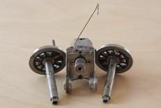
You can also make out that the crankpins are wired to the wheel rims. On this loco it's a trick to make the coupling rods 'live' which can help with pick-up. This can work well even on locos with conventional pick-ups. It needs thinking about though, particularly if your loco has outside cylinders and/or valvegear.
This page last updated 17/10/2010. Copyright © Euram Solutions and Steph Dale 2010. All Rights Reserved.
Steph Dale can be contacted through the contacts page