Back to Contents
Back to Railways Page
Link to Sitemap
BR50
50 3044-0
This loco was first started in early 2005 and was due to be finished as 50 2146-4. In fact the loco ran in that guise at the Upper Mill show in that year and was even covered on its own page, here. This might be considered 'page 1' of this story and shows the level of detail I applied to the model in that guise. As I mentioned in that description, the cab and chassis both needed more work and a set of etched plates were required. There was a further curve-ball: In early 2006 Gützold announced they were preparing to bring out a model of a BR58.30. So my plans to bash around various locos altered and the Neubau 2'2't28 tender fitted to 50 2146 would be needed for another project.
A search through a few books found a suitable candidate, 50 3044-0 running in 1974. This was an ex-ÜK (Übergangs Kriegslok) or austerity version that had received many of the standard parts and was now in very similar outline to the model of '2146, but had the smaller, Altbau 2'2't26 tender. There were a few differences, the square steampipes had been retained and would need making, the gutterline on the cab was higher and the grabs on the front bufferbeam were different. Not a whole load then; but enough to be getting on with. And at least it was in use earlier than the 1984 date of '2146 as modelled...
I started with the cab. There were a few changes required to this part. The original gutter was trimmed and polished off; a little filler was used to restore the profile over the cab side windows. The new gutter was made from plastic microstrip, simply stuck in place with a little MEK.
The fallplate is simply a panel of brass chequer plate with a short length of handrail wire soldered along its front edge. The ends of the wire fit into a couple of small handrail knobs, which in turn stick into the cab floor. As you can see, these parts were blackened before being fitted.
There is a little bit of work required on the tender, I replaced the grabs on the top of the tank, the ladders at the back and the handrails at the front. This tender body actually comes from an Austrian version of the BR50, so already has the higher coalboards required for the prototype. The chassis has had a little detailing to the rear bufferbeam, including fitting new lamps, hoses and grabs. The wheels have been replaced, courtesy of Weinert.
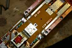
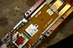
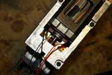
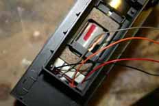
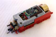
While the tender was dismantled for detailing I fitted the DCC decoder. In this case a Lenz 'Silver' was used as it provides all the motor functionality of the 'Gold' but in a cheaper package; of course in a loco this size I wasn't going to need a 'Power 1'. I made space for the decoder in the bunker by removing the die-cast coal and gluing the bunker moulding to the top of the tank. The fourth picture shows why removing the internal moulded 'features' from the bunker helped make the whole of the space inside it available for the decoder; I hadn't done it at the time the photo was taken. The pictures above show how the tracks need cutting to fit the decoder. Of course, if you're going to want to fit lights or smoke generators these areas will need isolating too. The red and black feed wires are soldered on to the circuitboard on the pick-up side of the break. The orange and grey wires are soldered onto the motor contact clips on the circuitboard; this can just be seen in the third picture. There is just enough room around the back of the bunker for the wires to run up over the motor. The decoder can then be retained with a sticky pad on to the top of the motor. A piece of lead sheet (flashing) was cut to make a base for the coal load; as it's over the decoder it makes sense to insulate the inside of it - I used masking tape. So that's it - reasonably straightforward and some ways less fiddly than the DCC-ready versions of the BR50 currently produced. Of course it gets a little more complicated if you're retaining working lights and/or using a smoke generator as the function wires from the decoder would need running to where they're needed.
Around the front of the loco the steampipes were made from layers of plasticard to make a strip of 4mm x 5mm, which could then be trimmed top and bottom to fit. Not an easy job to do; the second set I made fitted well enough and were then fixed to the smokebox with thick superglue. After it had cured off completely a little Humbrol model filler was used to finish blending the join with the smokebox. The bufferbeam detail was covered as part of the original build; putting in the front frames and guard irons, Kadee coupling, grabs and brake pipes. The set of 'pole' hand grabs by the lamps were pulled out, new holes drilled, and the loop grabs fitted. At this stage I also straightened the chassis; carefully bending the bufferbeam up got it to where it needed to be.
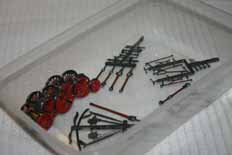
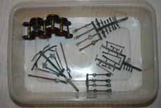
The chassis has been re-wheeled and detailed too. The wheels are the Weinert set which come highly recommended. Ditto the valvegear. I decided to wire brush and blacken the BR50 valvegear, and polish and blacken the wheelset. I did find that I had to use M1 screws from my stock to secure the return crank on to the centre driver; the ones provided weren't long enough to engage on the threads. I finally found a very simple trick to painting the fluting on the valvegear. I used the Weinert red cellulose paint; flooding the fluting with a small brush. This then dried in a couple of hours and I was able to use a cotton bud moistened with cellulose thinners and then blotted until it was almost dry to rub over the paint that got where I didn't want it. Very quick and simple, and if you work from the back of the sprues it's even easier. Unfortunately I don't think it'd work with enamel... :-(
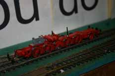
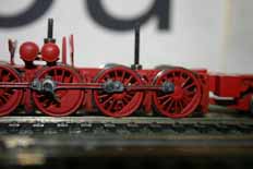
These couple of views were taken while the re-rodded and re-wheeled chassis was undergoing a running trial on my test track. With the top of the gearbox unclipped, finger power was used to push the chassis up and down to feel for any tight spots. Surprise, surprise; there weren't any. The body fixing screws have been used to hold the chassis together at this stage, a pair of spare M2 nuts standing in for the threaded body weight. The right hand picture gives a hint of what's to come and why replacing the wheels is so worthwhile. As an aside the new wheels also improve pick up of the loco chassis - the metal wheels allow the coupling rods to act as bus-bars passing current up and down the loco chassis.
The cylinders were detailed with a Weinert set and a few other small details added. As is becoming normal for me, the parts were all blackened before being fitted. The loco also finally got the valvegear lift links fitted as well; cut from a couple of pieces of scrap brass fret. The rest of the work on the chassis came down to a little plumbing, removing part lines, and careful painting.
So now it's ready for painting and weathering; and I need to get a set of 'plates etched up. Then I can do a couple more pictures to finish off this page...


