Back to Contents
Back to Tips and Tricks
Link to Sitemap
Preparing wheels for live-axle pick-up
A fast and furious run-down of how I make up wheelsets for locos that have live-axle pick-up. With particular reference to modern, British-made finescale wheelsets such as those made by Alan Gibson, Sharman or Ultrascale.
And yes; if suitable I use these sorts of wheels in both European and American models, as well as British! We start with inside-bearing wheel sets. Further down the page, outside-bearing wheels are covered, here.
Inside-bearing wheel sets
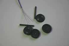
1. Parts required are; the wheels and axles you want to short and some fine wire. I tend to use 5Amp fusewire most of the time, but stripping wire from cable works just as well. The blackened wheel tyres and axles (courtesy of an Alan Gibson wheelset) will help you see what we're doing as we go along. You'll see!
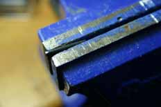
2. First thing to do is to put a slight draft on the axle where the wire will fit. The shiny spot on the end of the axle should give an idea of the size and shape required. There's another one on the other side of the same end of this axle because I use two wires. Better safe than sorry.
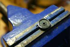
3. The wheel is prepared by being cleaned with emery paper, glass-fibre brush etc. so it's clean and shiny for soldering. At the wheel boss two small grooves can be cut in line with the polished areas - it gives somewhere for the wire to run.
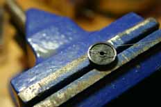
4. After tinning the end of the wire(s) the back of the wheel can be tinned where it was polished. Use a hot iron, plenty of flux and a fairly low temperature solder; 144° is fine. The aim is to get in and out without overheating the centre. If you can smell it or the wheel is too hot to hold then you've probably overdone it. Once tinned the wire can then be soldered onto the back of the wheel rim.
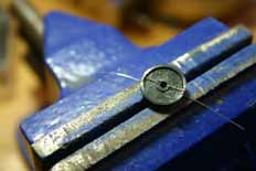
5. With the wires successfully soldered to the back of the wheelrim they can then be fed through the axlehole and gently pulled straight and taught through the grooves.
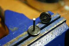
6. The axle can then be pressed home. As it goes into the bore of the wheel the axle will trap the wire. I tend to put small blob of a suitable retainer such as Ritelock RT01 or Loctite 601 on the end of the axle when doing this. Threadlock such as TL42 or 242 is also suitable (though less permanent), but don't use superglue! Of course, you don't have to use anything if you don't want to - I just prefer to know which wheel is going to move when I press the opposite wheel on. The last job is to carefully clean up the solder and wire end where it meets the rim. Careful work with a needlefile and some emery paper will take care of it.
Outside-bearing wheel sets
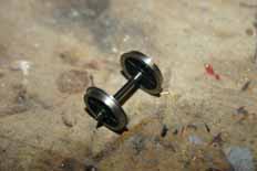
1. The technology used in the fabrication of the inside-bearing split axles as detailed above can be used to make outside bearing equivalents with a few small changes. The wheels used here are, once again, Gibson; this time destined for a French 38P tender. The wheels are trial assembled, in this case using a set of short pin-point axles. The wheels are gauged and made sure they're square on the axle and run well. All the usual stuff. On one side the axle is polished behind the wheel. This is necessary even if the axle is plain steel; if it's blackened like this one it's absolutely imperative.
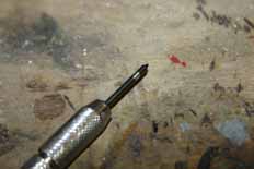
2. The wheels can then be removed from the axle and the shiny patch on the axle tinned. I held the very end of the axle in a pin vice as it allowed me to roll the axle around as I applied first the flux, then the solder and iron. Just as with the normal live-axle wheels the solder is an electrical multicore type used with a good quality paste flux.
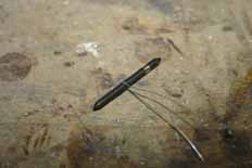
3. Now we're definately back in familiar territory! The short links are made from 5Amp fusewire; twisted around the axle one and a half times.
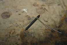
4. The wire can then be soldered onto the axle. Again; work cleanly and a little flux will help the solder run.
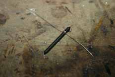
5. The wire can then be carefully unwound slightly so that you have a loop of wire soldered to the axle, with two wires coming off on opposite sides.
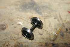
6. The wheels can then be re-assembled on to the axle. This will be in their final positions, so it makes sense to ensure they're accurately gauged and square on the axle.
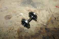
7. The wire tails can be tinned and the back of the wheel polished and tinned where the wire will be soldered. The wire can then be carefully pressed onto the back of a spoke and fed down to the rim where it is soldered.
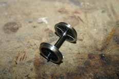
8. Trimming the wire and polishing off the excess solder is the final job. Take care that there are no lumps or bumps on the back of the flange that will interfere with the running. I normally use an oval file for this job, working around the rim. A quick check with a multimeter confirms that everything is connected as it should be. The wheels can now be blackened and/or painted ready for installing in your model...


