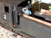
I normally begin with a photograph of the original model but I don't have one this time so here's a photograph of the completed cab and tender as an appetiser.
A photograph of the model used for this conversion does not exist in my collection but it is the Bachmann Spectrum On30 2-6-0 mogul. This was purchased as part of their Silverton Flyer start set together with three goods vehicles and a caboose. The locomotive being finished in the DRGW bumble bee livery. After reading the model press reviews evidence suggests that the model is based on an early Rogers or Cooke design. This is the earlier, in fact the first, of my On30 detailing escapades. A check of my original copy of (the SP steam modellers bible) Guy L Dunscomb's book A Century of Southern Pacific Steam reveals Locomotives that the SP either scrapped or rebuilt their narrow gauge 2-6-0s into 4-6-0s between 1924 and 1934. Despite this I pressed on with my exercise.
The Precision Scale O scale steam locomotive parts catalogue was ordered and duly arrived. However, I was not expecting it to be the size of a telephone directory. Having a penchant for the Southern Pacific I ordered as many SP narrow gauge parts as I could. I also desired a relatively modern Baldwin locomotive as the model is provided with early fittings. This is in addition to the fact that Baldwin built more narrow gauge locomotives than the other manufacturers at that time in history. This being borne out by a book purchased on my behalf by Steph - American Narrow Gauge Railroads by George W Hinton and published by Stanford University Press. This academic tome details the various historical aspects of the American narrow gauge railroad scene and was a worthwhile investment. Enough of the research and now onto the practical.

I normally begin with a photograph of the original model but I don't have one this time so here's a photograph
of the completed cab and tender as an appetiser.
As with all of my conversions and detailing projects the locomotive body was removed from the chassis and the chassis set aside to be dealt with later.
The boiler fittings and handrails were removed by pulling them off with finger strength which was very good as I didn't have to resort to a knife. Any pipework was even easier to remove, from what I recall there isn't any! This conversion was starting to look good already. Any small holes remaining were filled with Revell plastic model filler. The pilot was also removed by simply undoing a screw. The cab glazing was carefully removed and stored for re-fitting later.
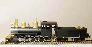
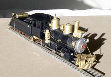
The photographs above show the new boiler and running plate fittings attached to the prepared boiler and the new
SP pilot attached to the chassis. The boiler fittings were attached using superglue and the pipework was formed
from brass wire and soldered where I could without damaging the plastic body. To ensure the air and steam
lines were correct I followed the diagrams in the Precision Scale catalogue and the Locomotive
Cyclopaedia (published by Kalmbach). The headlight was
soldered to the headlight bracket and a hole drilled through the bottom. A short
length of brass tube was inserted to enable a small light bulb to be installed. The headlight assembly was
fitted followed by the handrails. Injector pipes were also made up from brass wire and installed
underneath the cab
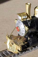
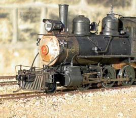
I made the new pilot from the Precision Scale brass casting and etched
chequer plate. These was soldered together with new front bar frames formed from 1.5mm square tube. The
ensemble was cleaned and screwed to the chassis to ensure accurate fitting. Kadee #803 couplers were installed and tested.
I also fitted the boiler stays from the smokebox to the pilot. Initially these were straight but were
altered after completion of the conversion and can be seen in the above photographs.
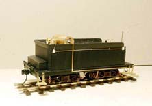
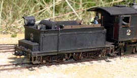
Although not evident in the photographs above of the modified tender, the obvious thing I noticed about the
original model is it sits when coupled to the
engine. This is of course to accommodate the original couplings. To raise the running height I increased
the depth of the bolsters underneath the tender by 1mm. After refitting the tender bogies this has the
desired effect. As a result the engine/tender coupling had to be adjusted. The other items
added to the tender to improve it's appearance were; an air tank, replacement water filler, back up light,
headlight, steps, lighting cable conduit, coal boards, safety chains between the bogies and underframe
and of course, couplers.
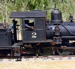
The cab was a relatively easy job which involved plating over leading side windows and the addition of
door handles. The plating was cut from thin brass sheet and the rivets embossed randomly using a rivet
press given to me by Steph (this turned out to be a useful tool). The result of which the plating looks like
home-made repair by the railroad. The four door handles were made up from short lengths of 0.7mm brass wire folded
at 90 degrees and one leg filed flat. These were fitted along with the glazing after painting the doors red to preserve the brass finish.
With the body nearly finished my attention turned to the chassis. All in all there was not much to do here except fitting the drifting valves to the cylinders. That's what I thought until my annoyance at breaking the plastic valve gear support bracket and creating unnecessary work. Taking the plastic one as a template I made up a new one from 1mm brass. Of course I could not fit this without it electrically shorting as current collection is via a split frame. To overcome this I made a mounting from plasticard and electrically separated the new bracket by cutting it in half to give two equal pieces into which I drilled four holes. These were sandwiched between two pieces of plasticard with araldite epoxy resin and held with plastic pegs through the holes drilled earlier. An 'L' shaped piece of brass was fixed to one side of the centre of the bracket to provide a means of mounting this, with a layer of insulation, to the chassis. With this fitted I soldered the slide bars to the bracket ensuring the valve gear operated smoothly. This is one job I could have done without but it turned out to be a blessing is disguise by way of an stronger bracket.
Following the unexpected work above the body was finally mated with the chassis. Prior to coupling the tender I installed a Zimo MX64 decoder and home built power pack. A detailed description of which can be found within the DDC pages of this website. After this, the model was painted Polly Scale Engine Black, Humbrol Gunmetal for the smokebox and chimney, and Humbrol Aluminium for the smokebox door. When dry decals were applied to the cab sides, tender rear and the headlight numberboards. Testors Dullcote was used finally prior to the fitting of the smokebox numberplate and weathering using my now time honoured technique of applying washes of artists acrylic watercolour paints.
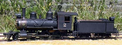
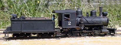
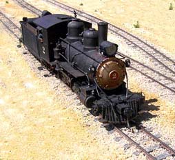
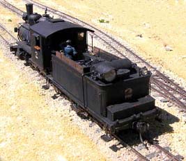
The photographs here show the completed Baldwin mogul after fitting the Baldwin works plate.
As alluded to towards the beginning, this is the first 'O' gauge model that I have detailed and modified and proved to be most satisfactory. Now onto the next one...