Back to Contents
Back to Railways Page
Link to Sitemap
BR18.2
02 0201-0 and Auxiliary Tender
When first given an auxiliary tender 02 0201-0 was given a tender from a withdrawn BR01.5, with few modifications. Other than the required connections between the loco and the tender - including a full bufferbeam - there seems to have been very little involved. So the question is then how to build a good model of an 01.5 tender...
I started with a spare Rivarossi tender, one from either their BR01 or, in this case, from their BR39. This provides a nicely detailed, free running tender as a starting point. I added the oil bunker from plasticard using the one from the Weinert DR BR44 as a set of templates. In this way I knew that Weinert detail parts would fit. Unfortunately the full set of DR oil tender details are not available seperately from Weinert so some of the details had to be scratchbuilt. But; many of the trickier parts are either generic, or can be obtained from the Weinert parts list.
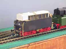
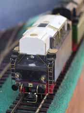
To start with, the lid and back of the bunker are grafted on to the Rivarossi moulding. This provides a good basic starting point for the body. At this point I reduced the height of the bogie mountings to get the ride height correct. This meant cutting some fairly large chunks out of the underside of the tender to clear the wheel flanges.
As I was unhappy with the moulded details of the rear bufferbeam that detail was all filed off. It allowed me to make front and rear detail uniform, in both cases courtesy of a smattering of Weinert parts. Before using the big file to clean up, a pilot hole was drilled through the original buffer shanks into the bufferbeam so that the replacement buffers went in the right place later on.
Most of the remaining details in this shot are from Weinert. Obviously things like grab handles had to be made from wire (0.4mm dia half hard brass). The guard irons are home brewed as the Weinert ones come with a set of tender brake gear. The Rivarossi truck frames are such good mouldings that I didn't feel the need to re-detail them other than add a couple of brake rods which helps strengthen the frames. Don't add the pull rods until after the wheels have been blackened though - you'll never get them out (or back in again!).
The changeover valve on the frame is melted into the plastic with a warm soldering iron; slowly and with a lot of care.
All the ladders are made from the same Weinert part. Those for the sides of the bunker are made by filing and bending a set for the back of the tender. One of the cases where the proper part wasn't available off the shelf.
And while I think to mention it; the lamps are nothing more than sections of brass tube...
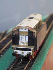
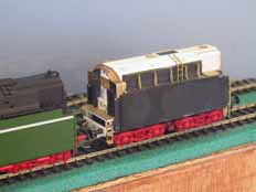
It's at this end where most of the scratchbuilding needed to be done. You can see the white plasticard where the front of the oil tank was fitted into the body, similarly the footplate, front part of the frames and bufferbeam needed adding from scratch. The brass on the footplate is some of Weinert's excellent chequer plate - a useful 'stock' item.
Unfortunately the cowl/draft screen isn't available as a spare either, so that was made from a few bits of brass; cut out with a jewelers piercing saw and soldered together. Likewise the hatches on the tank top had to be made from discs of brass. The front one has hinge straps from a Scale Link etched brass sheet added, and the rear one is embossed to portray the fixing bolts. I also had to make the valve sets on the front of the oil bunker, once again I used the Weinert details from the BR44 kit to provide an example I could follow with a few bits of bent and soldered wire.
Thankfully the front steps and handbrake were both available. I ordered one of the DR frets that contains things like the cab roof skylight and mesh, this also usefully contains the walkway mesh for the top of the bunker. It's not shown fitted in this picture as I decided it was best left until after painting.
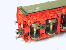
I thought it might be worth including this view here as well. I use Kadee couplings on most of my stock as they allow a wonderful 'hands off' style of operation. But this vehicle was going to see most use on 'Prutz', a large Austrian layout that uses the normal European coupling as standard. So a useful side-effect of building the auxiliary tender was that it gave me a coupling conversion, with consequently less handling of the Roco loco. The front coupling (a #18) is mounted in a fixed NEM style box built into the front of the frame as I went. Don't be tempted to use a fixed box if you use close couplings though!
You can also see the brake rods I mentioned earlier and the blackened wheels. Note that the original pick-up springs are left in place; I found it ran better that way. Incidentally the blackening is done using Birchwood Casey Liquid Gun Blue. Great stuff, even if more than a little toxic...
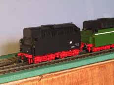
Mum; I've finished!!! Paint by Humbrol for the body, Molak for the chassis. Decals by Weinert - a spare BR44 set supplemented with yellow warning panels from a Gaßner set. Varnish is Ronseal satin varnish. The etched numberplate was one of five(?) supplied for the 02 0201-0 by VS Modellbau. Lucky break huh?
Have you noticed the subtle detail change on the back of the Roco tender? Taking the oil filling derrick off has backdated the loco from Era V to mid Era IV. The lamp is a Weinert spare - fitted into one of the mounting holes already in the back of the tender body...
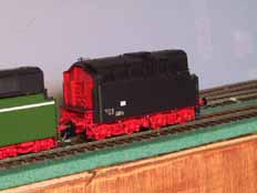
I wonder why the DR painted the front of their oil tenders red? A visual reminder maybe? Perhaps it made it easier to see if there was a leak.
Once the loco has had a bit of tarting up then I'll weather both the loco and tender...


