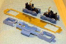
So here we are. One set of trucks and frame from a scruffy Southern Pacific SW1500 and a lump of brass. I'm not quite sure how I'm going to rebuild the SW1500 if it's ever needed to run with my Espee stock, but I guess that'll be another story!
One of the most distinctive aspects of the average Canadian National GP9 is its trucks. Most GP7s and GP9s CN used had lightweight EMD flexicoil trucks. These are shorter wheelbase than the conventional Blomberg 'B' and are a truck type shared with (hint, hint) some SW1500 switchers.
Having established that the job is a bit more involved than just swapping some cosmetic truck sideframes around I went out hunting for an Athearn SW1500. To be honest, at the time of writing they're not that easy to come by. There are rumours of Athearn introducing an improved model under their Ready-to-Roll line, but the original Blue Box one is perfectly adequate for our means. Primarily I used the trucks and the frame. You could use the motor, but I decided to use a spare P2k motor I had left over from re-motoring an FA-2. The hope is that the performance will be close to my other P2k GP7 and GP9 models.

So here we are. One set of trucks and frame from a scruffy Southern Pacific SW1500 and a lump of brass. I'm not quite sure how I'm going to rebuild the SW1500 if it's ever needed to run with my Espee stock, but I guess that'll be another story!
As you can see, the Athearn frame was cut into three chunks with a junior hacksaw - high tech stuff this! The brass plate is about 40/1000inch (1mm) thick and is a grade known as 'engravers plate' or 'engravers brass'. I use this particular material because it tends to be harder and flatter than normal rolled brass sheet, therefore it's easier to saw, file and assemble. It's also reasonably sturdy but will benefit from some reinforcement as we go. This blank has been cut out with a fretsaw using size 0 blades then trued up using files. For a piece of brass of this size and relatively simple shape I crack out some decent size files; 10 and 12inch, rough and second cut.
I'm not going to give a blow by blow account of what I did - but I think it's worth taking some time to explain the principles I've used. This is definately one of those cases where just following the dimensions wouldn't necessarily lead to successfull model. The techniques are worth thinking about in case there are other Athearn mechanisms that you may want to alter in this way.
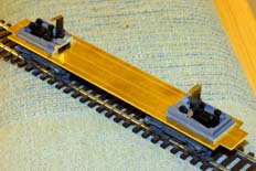
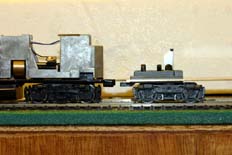
After getting the basic body assembly done, as reported on the previous page, the brass baseplate for the chassis can be cut out to fit. I made the best effort I could to end up with something that was square, parallel and had good, clear and accurate centre lines (both lengthways and crossways). From this the truck centres were marked and lines developed from there to mark out the area that needs to be removed for the sections of Athearn SW1500 frame.
The Athearn frame has a ledge along its bottom edge that is useful for sitting the brass frame on. The two views above show how the brass frame drops onto these ledges on the Athearn frame sections. This is part of a trial - I wanted to see what the ride height of the chassis would be and so the cut outs in the brass aren't quite right yet. However, the ride height is; the comparison with a P2k GP9 chassis shows that the top surface of the brass is pretty much level with the top surface of the P2k frame. That's a result!
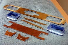
Here is a full set of the thick, structural elements of the chassis. All the brass parts in this view are made from the 40/1000inch (1mm) thick engraving plate, cut out as previously described:
All the parts have been identified with 'F' and/or 'R', for Front and Rear, respectively. As this is a Canadian National loco it operates long hood forward...
Also shown in the picture are the two sections of Athearn SW1500 frame. As you can see they've been further modified to improve their fit. The corners have been cut back to clear the inside ends of the body shell and the front section (long hood!) has been narrowed to 18mm, again to clear the 'shell. I did this by attacking it with a minidrill and dental burr which was adequate enough to do the job, including cleaning up with a great big file, in around 20 minutes. Thankfully the rear section under the short hood doesn't need doing as the cab base and battery boxes offer plenty of clearance. A further modification was to remove a thickness equal to the ledge from the lower front corners and rear of each piece. This is a job for a large file. Removing this extra material allows the Sub Frame and Coupler Mounts to overlap with the Athearn frame section, so giving greater strength to the chassis. Again, some of the later pictures during assembly should help make this clearer.
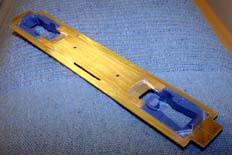
This is the view after the SW1500 chassis sections and Sub Frame have been fitted in to the Main Frame. In practise the Athearn parts were fitted and allowed to cure before I fitted the Sub Frame. You can see in the picture how the Sub Frame overlaps the Athearn parts and so provides reinforcement of the join between the parts.
In all the chassis assembly work I've used DevCon '2-ton' epoxy resin as an adhesive. The parts have all been keyed up on their gluing surfaces with rough emery paper and then degreased with lighter fluid. This keying and cleaning routine is carried out on the bonding surfaces just before assembly - once the lighter fluid has evaporated away completely the adhesive can be mixed and applied. It's worth taking the time to clean up the parts after the initial cure of the adhesive. Either a razor blade or a curved scalpel works well to trim any excess resin away.
The die-cast parts were gravity held as the adhesive cured. Wanting to keep a good, strong bond between the Main Frame and Sub Frame these parts were clamped using toolmaker's parallel clamps. After the assembly had completely cured the holes shown were drilled in the Sub Frame. They're not particularly critical for positioning as they're only there as starting points for the piercing saw to cut the motor clearance from the Sub Frame.
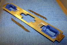
The motor clearance is trimmed out from the Sub Frame after sticking it to the Main Frame. It's a simpler job to stick two parts rather than three and keep them in good alignment. Running a piercing saw around the inside of the motor cut out and then cleaning up the resulting hole isn't tricky as the Main Frame can act as a guide.
It should now be pretty clear how the Frame Runners attach to the rest of the chassis and strengthen the motor cut-out - and why they need to be made in the thick material. You can also see why the step section is in the top of their profile; it locates in the cut-out.
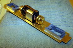
I thought I'd better do a quick trial fit of the motor to make sure it's got good clearance all the way around it. So the Frame Runners were put in place without any adhesive and the motor lowered into the cut out. You can see it's only a temporary installation as the flywheels are actually touching the Main Frame.
The build continues on the next page...