Back to Contents
Back to Railways Page
Link to Sitemap
CNR F3A (F7Aum)
Class GFA-17a, #9171
Or; some suggestions on building the Highliners F-unit kits...
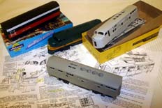
The starting points and the main assembly items are the Highliners bodyshell kits for the F-units. The top right of the photo shows an un-assembled a-unit kit and in front is a b-unit (for a T&NO F3B Phase III) quickly mounted on an Athearn F-unit chassis.
Just so we don't get the wrong end of the stick at this early stage I'm going to use Athearn's 'Blue Box' kits to power the Highliners models. The plastic Blomberg truck frames of the Athearn model are superb and the mechanisms are all wheel drive. I'm still going to tweak them to improve the appearance and running, but they're a good starting point. Their low cost and relative ease of procurement is the main reason I chose to go this route. Athearn Genesis, Proto 2000 (+1000), Bachmann, Stewart, Kato and Intermountain all produce F-unit chassis which could be used (with varying degrees of success) to power the Highliners bodies.
And if all those manufacturers produce F-units why would you want to build a kit? Well, the Highliners bodyshell is the F-unit model in HO. Forget brass, forget other manufacturers; the best is the Highliners kit. Interestingly it's also part of the reason that the Athearn Genesis model isn't available undecorated - they use the same bodyshell mouldings. There is another consideration; you may want to model a specific version that's unlikely to be made by one of the major players. If that's the case it's reassuring to know that the best is so easily obtainable!
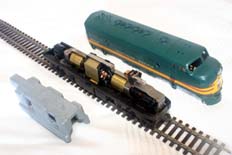
Here's the Athearn F7A model with the body unclipped. The chassis is common to both a and b powered models. The frame itself is common to all F-units, powered or unpowered. The heavy weight in the foreground just sits on the chassis and is retained by the body clips. It either needs to come out, or have a slot cut in the top of it if you're going to use a Highliners 'shell. The old Athearn body doesn't look bad at first sight either does it? However it does show its age now with poorly defined grilles, the caricature of the front window shape, and dimensions which drift quite strangely.
Most of the work of this build is actually in modifying the chassis frame to fit the 'shell. It's not actually all that difficult to get the Highliner 'shell to fit correctly at the correct height. For a really refined model a little more can be done. And this F3A has had part of its skirt over the fuel tank cut away, so I've done that too. For most F-units you probably won't need to bother!
A quick fit of the Athearn chassis to the Highliners bodyshell.
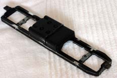
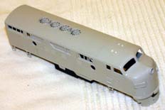
And this is the simplest way to fit the two parts together. Snap or cut off the clips on the fuel tanks and file smooth. The little clips on the frame can come off too - I used a dental burr (carefully!) in a mini drill to do that as I thought using a file might result in unintended damage to the bogie pivots.
That's pretty much it for the 'simple' method. It works for both a and b units and you'll find that the body will sit slightly too high on the coupling mounts. And you'd probably need to use underset, short Kadee couplers #44. And I'm not sure how you'd retain the body on the chassis. So in my book it's not quite reached the minimum acceptable standard...
A method to get scale body height and a better coupler height.
An alternative method for fixing the body and chassis together is to use the couplers themselves. This requires a further modification to the chassis, but allows the use of the Kadee 'scale' coupler and you'll also need to order the draft gear castings from Details West. They're available in detailing set for the Highliner and Intermountain 'shells, which includes numerous other parts and is highly recommended. The next few paragraphs cover how to make these few changes.
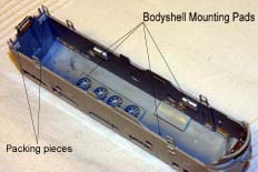
There are a couple of small changes to make to the bodyshell if you want to fit the Athearn chassis at the correct height. The first of these is to put a mounting inside the bodyshell so the chassis sits at the correct height. I used 5mm x 10mm pieces of 40/1000" (2mm) thick plasticard. These need positioning 5.25mm up from the bottom edge of the body shell. I made a quick jig to guarantee consistent positioning of the four pieces. Their final position is shown in the photo. You'll also have noted the two squares of 20/1000" (0.5mm) thick plasticard along the back wall of the body - this packs the chassis forward so that the battery boxes cast into the Athearn chassis align with their access panels moulded into the body shell skirt. This also gives clearance to get the chassis past the rear coupler mount. You may need to round off the front of the chassis to clear the inside of the pilot too.
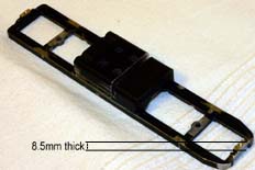
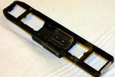
Now the coupler mountings can be modified to fit the bodyshell better and allow the fitting of the 'scale' couplers. The first thing to do is to cut the ends of the mountings off completely (junior hacksaw) and file the area smooth. The coupling pads are then filed down so that the thickness of the pad and frame is 8.5mm. You'll need to keep the surface as flat and square as you can. Finally the centre of the remaining pad needs drilling and tapping to take an 8BA screw. I drilled through the whole thickness with a 1.5mm drill before going about half way through with a 1.8mm (8BA tapping) drill. The hole is then tapped to take the 8BA x 1/4" screw. And that was it for the front; not so for the rear. In order to get the coupler closer to scale distance I ended up re-mounting the coupler...
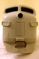
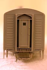
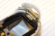
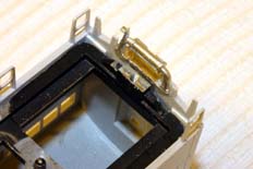
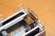
And here's a set of views showing how the draft gear fits the Highliners 'shell. The draft gear is fitted to the loco after being cleaned up. You may find that further trimming is necessary to get the coupler boxes and chassis frame lined up with the cut out - this is easier done once the draft gear is fixed in place. Compare these photos with the castings in the kit (or the photos on the Details West website) and you'll see what I mean. The difference between the fourth and fifth photo shows the change I subsequently made in order to get a closer rear coupling distance. It's simply a piece of 40/1000" brass I drilled a hole for a piece of brass rod that would go down the 8BA hole I previously put into the chassis. The rod was soldered in to the brass. Once it had been cleaned up the parts were bonded to the chassis and then the new fixing hole drilled and tapped.
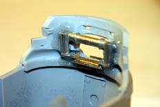
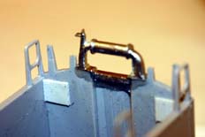
Both Details West and Highliners recommend securing the draft gear with a good quality epoxy. I used Devcon 5-minute with all the mating surfaces keyed up with coarse (150 grit) emery paper. I actually used a damaged Kadee coupler box to align the draft gear as the adhesive cured. Once it's all hardened off the coupler boxes can be threaded through the Details West draft gear which then forms a loop loosely retaining the chassis.
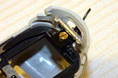
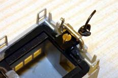
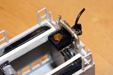
And this is how it all fits together. You can see how the coupler boxes are slipped through the draft gear casting. For the shorter coupling on the revised mount the coupler is a #158. The back of the box is trimmed very short to clear the bogie and the flange is filed off the front of the 'box so that it can sit inside the draft gear casting.
I thought that a word or two on couplers may be helpful here. Both Dave and I use the Kadee #58 'Scale' coupler as routine. In a few odd cases that has meant modifying models to take them. This model has left me with no real choice of how to mount the couplers, so thank goodness Kadee have now bought out short (#153), long (#156) and medium (#158) versions of their 'Whisker' coupler with the 'scale' knuckle. Unless otherwise mentioned the photos on this page show the model fitted with a set of #58 couplers I had floating around; #158 would retain the same length.
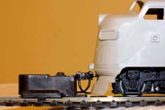
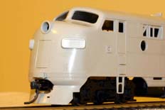
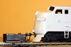
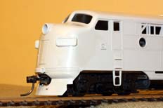
At the nose end of the modified chassis a medium, #58, #158, coupler puts the knuckle in pretty much the correct place for scale appearance. If I was using this loco as a lead engine in a consist I'd be happy with that. I'd probably remove the trip pin from the bottom of the coupler to further improve the appearance. But, as the photo on the left shows; the trip pin of any facing coupler fouls on the pilot, so the knuckle won't close! I'll be putting a long, #156, in there so I can still shunt with this loco if necessary. The two photos on the right show the loco with the #156 coupler installed.
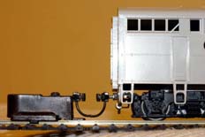
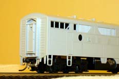
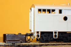
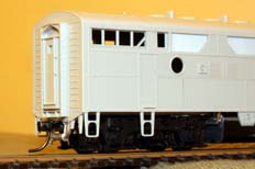
Meanwhile, at the rear of the loco, the height is still shown to be okay. In this case though the knuckle sticks out a bit too far. So a short, #153, was tried to give good appearance when in a consist. In practise this still wasn't really close enough; hence the rebuilt coupler mount referred to above. The rebuilt mount uses a #156 coupler and gives a very short distance, with the 'palm' of the coupler directly in line with the back of the gangway. The revised coupler position is shown in the two photos on the right. Operationally the coupler will be fine with no pilot to worry about.
The next page will deal with the re-powering of the chassis and a couple of slightly 'heavy duty' chassis modifications that will help improve the appearance for certain variants. And we'll actually get cracking with the details specific to #9171...


