Back to Contents
Back to Railways Page
Link to Sitemap
BR(S), SR, SECR L-class 4-4-0
#####
This was always going to be fun. One of my absolute favourite locos is the SECR L-class, it's probably not the most elegant loco in the world, but it has an undeniable 'correctness' in its appearance; at least as far as I'm concerned. And having pretty much decided to give up modelling in 4mm scale it was going to have to be in 0-gauge. This would be fine, if a kit was available.
So here we go with the build. It probably won't surprise you to know that the specification for this model would include the best transmission I could find, DCC, sound and between-the-frames working valvegear. And therefore I would need good drawings - ideally general arrangement and part drawings. I found some; the list of references is appended at the end of this piece. I also found that Wainwright's locos did use some standardisation, not as crippling as the Swindon variety but it did allow me to use info for other of his locos (and particularly his tenders) for some parts and ideas.
A tender, behind.
One area where the design seems to demonstrate logical evolution is in the tender. This is useful on two counts; there are kits of some Wainwright tender locos available, and there are two Wainwright tenders preserved. Unfortunately both the preserved tenders are fairly early examples. One is attached to the C-class 0-6-0 on the Bluebell Railway and the other is behind the D-class 4-4-0 in the National Railway Museum.
I managed to find a few good pictures of the C-class tender through the Bluebell Railway's excellent (if slightly scatological) website. Enough for it to be obvious where the differences between the L and C tenders where. Combining this with a few dimensions culled from various publications and it became obvious that a later tender, such as fitted to an E-class 4-4-0 may be a good starting point. Well David Andrews does an E1-class 4-4-0; would that be good enough? And could I get one separately?
Actually, yes I could! So off we go; a bit of progress. The description that follows is a mixture of the tweaks I applied as preferences, detail enhancements or conversions to the kit to better represent the version running with the L-class.
At this point I feel I had better come clean. During the build of this tender I managed to prove my Father's maxim 'assumption is the mother of all cock-ups'. And although I wonder why he's got it in for male chickens it is, to an extent, true. I had made assumptions about the tender brake links, placement of the vacuum cylinder, vacuum reservoir(s), guard irons and the layout of the coal bunker. And although all were entirely reasonable and plausible they were equally wrong! So what you'll see below (at least for the chassis build) will be a set of chronologically correct descriptions of what I did if I hadn't made the first set of 'cock-ups'. These are illustrated with a range of photographs that will show the pertinent details; but may not have been shot in the order presented! I apologise for this but it goes to show the value of working from decent source material, that I don't always get it right and that brass is a very forgiving material to work with - I'm very pleased with the end result.
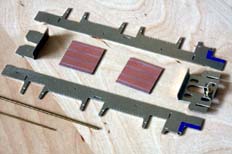
In recent years I've found that sprung split-axle pick-up systems offer a number of advantages. Not least reliable, low friction pick-up; which makes them ideal for trailing wheels. Though I'm still not sure I'd use them on a driven axle as isolating the gearbox strikes me as being a bit of a fiddle. Slater's original plastic hornblock sets (item 7960) consist of a plastic (glass-filled nylon?) hornguide with a brass bearing sliding in it. We'll come back to them later but I thought I should draw out now that, despite what some will tell you, you don't need to electrically 'gap' the chassis - just as long as each bearing is insulated from the frames. This also means that the copper-clad paxolin shown in the photo above is there mainly to act as a spacer and to anchor the wiring and bus-bars later.
If you've got an E1 tender kit in front of you the comparison with the photo above will show that the slots in the frames have been opened up for the hornblocks. I cut the slots out to the areas marked with half-etched lines on the frames. Although they're very good for height they are too wide for the Slater's hornguides. If you cut the slots to fit you might find it makes life a bit easier to fit the hornguides later on. If not there is a recovery, detailed below, which might even be more accurate in terms of alignment; though it is slightly more fiddly to do. Ideally the front needs trimming down to the height of the front dragbeam where marked and this can then be carried back under the mountings for the front brake crossbeam. I wish I'd worked this out before I did - I had the chassis completely assembled before I realised there was so much to be gained by trimming the frames back. There has also been a slight modification to the rear spacer to clear the coupling (when it's fitted) and it's also been drilled with two 0.9mm holes to take the ends of the brake hanger wires later on.
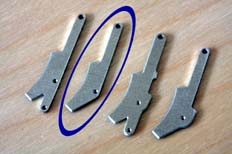
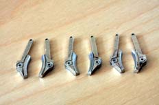
It's worth preparing the brake shoes as a set of sub-assemblies at this point. There appears to be a touch of over-complication of the brake pull-rod arrangements in the David Andrews kit (I hope he won't mind me saying so!). However, as the parts are accurately drafted it makes sense to play around. In the first photo you can see a variety of the brake shoe/lever assemblies. To put it simply you'll need six like the one with the blue circle round it! I drilled all holes in the brake shoe/lever assembly for 0.9mm wire as I thought the 0.7mm wire mentioned in the instructions just looked too skinny - the extra heft of the thicker section helps with the assembly later on too.
The second picture aims to show how I filed away a section of the brake shoe edge - this provides flange clearance. It's not 100% necessary, but better safe than sorry, especially as there's compensation and (hopefully) a little sideplay in the wheels. The set of 'shoes for the middle set can be seen to have slightly more removed; that's because I set up my sprung chassis to allow more sideplay and vertical travel on the centre axle. That aspect of chassis set-up is something we'll come back to when we level the chassis off.
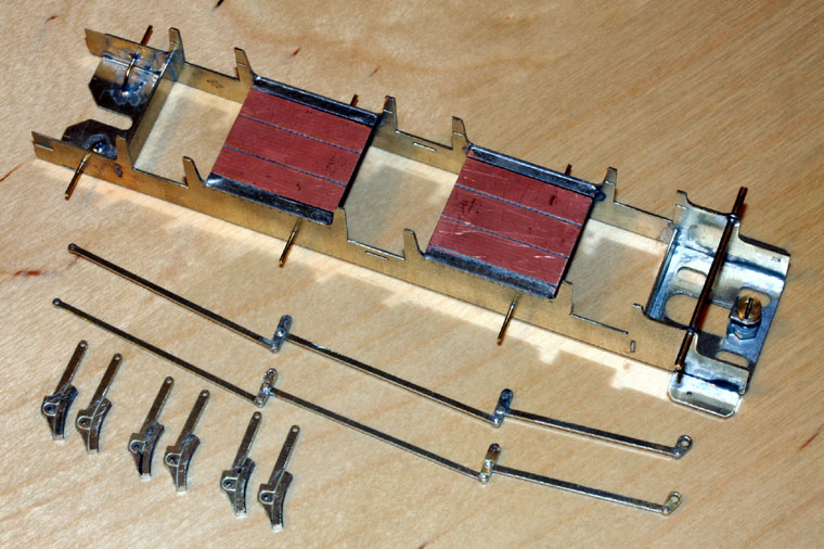

So that's the chassis together. All pretty conventional in terms of assembly; solder the front spacer to one frame, the rear spacer to the other frame. Make sure they're square (in both dimensions) and then assemble the two items together. Check it's square and parallel and then solder in the two paxolin spacers. The wires can then be threaded through, leave the front brake cross beam (1.6mm dia.) off until the brake links (see below) have been made. It is worth soldering in the front and middle brake hanger wires (0.9mm dia.) at this stage. Similarly, the rear brake hanger wires (also 0.9mm dia.) are formed to thread through the holes in the frames and the extra holes we drilled in the rear spacer. This latter modification will give a nice, strong set of hangers whilst keeping the rear screw fixing and coupling clear.
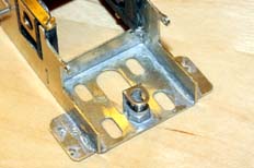
And so to the first of the twiddly bits - now with the photos waaaaay out of sequence so please ignore the fitted hornblocks; in an ideal world I wouldn't have fitted them yet! The photo above shows the front of the tender as it should be at this point - the front of the frames have been cut back and some of the mounting holes for the details have been drilled in the spacer. One of the holes so drilled is that for the handbrake - mark the location for the hole on the top of the front frame spacer by dropping the tender tank platform on to the top of the chassis and marking through the hole where the brake standard fits. After the mark is made it's then a relatively simple job to drill through with a 0.9mm drill.
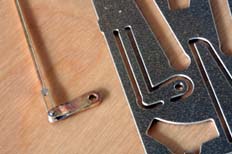
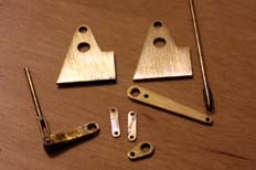
I wasn't hugely impressed with the handbrake lever but at least one is provided, unlike the rest of the links. The new handbrake lever is made from two layers of 16/1000" brass forked at one end for the link (a strip of 10/1000" brass) and the rod (0.9mm dia.). It's longer than the old one to fit the chassis and the new mounting hole marked and drilled in the previous stage.
I ended up making a lot of extra detail to go under the tender - particularly around the front. I started with the brake linkages. I should point out here that the brake cylinder will not be fitted as on the prototype it sits up in the base of the tender frame over the front axle and cannot be seen from any normal viewing angle. So the parts were cut out as follows - two brackets (top of picture) 30/1000" brass, long brake lever (middle right) 30/1000" brass, short brake lever (middle, bottom) 30/1000" brass, lift links (centre) 2off 16/1000" brass. Vacuum piston rod (right, top) 0.9mm wire and a short section of tube to fit. And the handbrake lever (bottom left) as previously described...
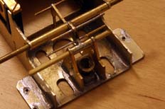
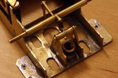
The first job for the assembly is to get the brackets in. They're 6.5mm apart and level with the front of the frames. Once they're in place sections of 1.6mm id. tube can be cut off to space the long and short brake levers. It's then a case of threading the newly made parts together with sections of tube onto the 1.6mm rod used for the hangers. The smaller parts are joined together with lengths of 0.7mm wire. The wires are all left long at this stage; it helps to ensure that the parts are parallel and square. By the way; assembling these parts should still make it just about possible to get the drawbar screw in place.
And once the parts are considered to be satisfactory the ends of the wires and pins can be cropped off to length leaving enough exposed at each end to portray the shaft end, bolt, rivet or whatever - remembering that the rod passing through the frames needs trimming to just fit between the outside frames. Which means that now is a good time to decide which spacing you're going to use for the outside frames (two options are given in the kit), I went for the narrower close-to-scale option, accepting that I'd need to make allowance around the buffers when the time came.
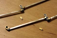
The next job is to prepare the brake pull-rods. On the D, E, D1, E1 and L class locos they run down the back of the wheels. The parts as provided are shaped to portray both the pull-rods and the short levers that (on the prototype) equalise the tension. It's a good idea as it keeps the assembly of the brake parts very accurate and consistent, but I decided I wanted a bit more detail in this area. I quickly decided to retain the accuracy of the part - so separating the elements was out - instead I used sections of scrap fret ; much of the frame around the body parts is (usefully) formed from 1.5mm wide strip. I ended up making 18 little rod ends from one strip; you'll need 16. They're shown assembled above, together with the two spares! It's worth the effort in my book: forming the rod ends, fitting (together with 0.7mm wire rivets), fettling, only took me an hour once I had a little production line set up for them. The holes for the brake cross wires were all drilled for 0.9mm wire too.
The photo also shows the detail added to the front crank - this I believe is largely incorrect as there should be a slack adjuster in the rod between the crank and the first lever. Unfortunately there's just no space to model these items properly as they have to fit the very restricted clearance between the frame and the back of the wheel - shame really.
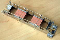
I then quickly did a check assembly of the brake shoes and pullrods and was so pleased with myself I decided to take a picture. Actually it's quite useful as it shows how the brake gear assembles, that it's accurate and that it's self supporting. Fiddly to get it all together though - bluetack or similar may help you hold it together for this trial run. There's one little job remaining before we get to fix this lot together...
It's worth putting some spacers on the spring hanger wires to help hold the brake shoes the correct distance out from the frames. You could buy some tubing with a 0.9mm hole down the middle, cut it as accurately as possible to the correct length, or you can do what I did and invest in a roll of 5Amp fusewire. This can be wound around the brake hanger, altering the number of turns changes the spacing. For my chassis I found that 16 turns was required to get the shoes in line with the face of the wheel. So having got my 16 turns on, the wire is pulled tight, tied off and soldered - plenty of flux, good clean iron, small blob of solder, in and out fairly quickly - repeat as necessary. Then trim off the excess fusewire leaving the hangers long for the moment. Job done.
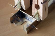
And here you can see what it's starting to look like. On the left is a shot of the back of the chassis, clearly showing the modifications to the rear spacer, brake hangers and their fusewire spacers.
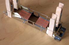
The second picture shows how the pull-rods are clipped and spaced with paper to the frame, ready for soldering. They've been set up in the frame with the brake shoes fitted to determine that the whole thing will fit together. It does.
You can click here for the next page about building the L-class tender.


