
1. We start with making the 6-pin NEM651 socket. Mark off a 10mm strip in 60/1000" (1.5mm), or thicker, plasticard. The marks for the six pins are put in now - I could have made a jig for this.
When converting a loco to DCC it's great to be able to try different decoders to get the best performance; particularly with locos that are home-brewed or converted. But it can be a fiddle to keep changing hard wired connections on those locos that don't come with standard 6-pin NEM651 or 8-pin NEM652 sockets. The solution? Make up your own sockets...
6-pin NEM651 sockets are at the top of the page; 8-pin NEM652 sockets towards the bottom, here.
1. We start with making the 6-pin NEM651 socket. Mark off a 10mm strip in 60/1000" (1.5mm), or thicker, plasticard. The marks for the six pins are put in now - I could have made a jig for this.

2. Deepen marks for pins into shallow grooves. These will take the wire sheathing later. The 0.6mm holes are then drilled in a line across the strip section. Snap strip from stock.

3. Cut off the section with the holes - around 5mm wide. The wires can then be prepared - they’re the sort of wire used for decoders and they’ll need tails in the region of 3mm long. By the way - the 'decoder' shown in the pics is actually the dongle from a Fleischmann BR22.

4. The wires are fed through the holes, turned over sharply and the sheathing is superglued in to the pre-cut channels. A little epoxy or more superglue can be used to form a bead over the sheathing. Leave to cure thoroughly.

5. The ends of the tails are quite scruffy at this stage and should be trimmed off against the hole. A quick continuity (or more accurately - lack of continuity) check is advisable at this stage to make sure none of the wires are touching.

6. The socket can then be installed into the loco - in this case my ÖBB 2067 with its scratchbuilt chassis. You'll note how the decoder sticks up out of the socket, unfortunately this sometimes allows the decoder to vibrate loose when the model is on its side (or upside-down) in its box. Thicker plasticard would help hold it more securely. Using the correct colour coding for the wires helps enormously...
With a Zimo MX62 decoder installed it's done!
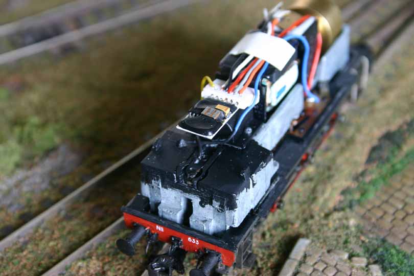
There's a picture of a slightly different socket fitted to Dave's NS 600 here.

1. The parts for the homemade NEM652 socket are Maplin items FL17T (stripboard) and DC17T (modular connector strip). You'll also need wire to connect it into your loco. For clarity we've used the correct colours (flash eh?). Oh yeah; and a decoder with an 8-pin plug. That's a Zimo MX61 in the picture...

2. The stripboard is cut into squares 4-holes by 4-holes at a minimum. Larger pieces can be cut to allow for fixings etc. It needs the four tracks cutting down the middle with the edge of a triangular needle file before soldering in two sections of the socket strip. An old plug unit can be used to hold the socket strip sections in the proper alignment while soldering.

3. Front view of the completed, wired, socket...

4. ...and here's a view from underneath. This can now be stuck into the model where it's needed - foam centred 'sticky pads' are a good idea. A version of this board has been used in my Märklin BR 212, which uses a Zimo MX64 and a capacitor power pack.